Let There Be Light!
Activity 2 | Week 3 | Background
\[ % \newcommand\v[1]{\vec{#1}} % \newcommand\v[1]{\mathbf{#1}} \newcommand\v[1]{\boldsymbol{#1}} \newcommand\vdot[2]{\v{#1}\cdot\v{#2}} \]
\[ \newcommand{\dd}[2][]{\mathrm{d}^{#1}#2} \]
\[ \newcommand\f[2]{\dfrac{#1}{#2}} \newcommand\da[2]{\dfrac{d #1}{d #2}} \newcommand\daa[2]{\dfrac{d^2 #1}{d #2^2}} \newcommand\pa[2]{\dfrac{\partial #1}{\partial #2}} \newcommand\paa[2]{\dfrac{\partial^2 #1}{\partial #2^2}} \newcommand\pab[3]{\dfrac{\partial^2 #1}{\partial #2 \partial #3}} \def\half{\frac{1}{2}} \]
\[ \newcommand\ket[1]{\left|#1\right\rangle} % |x> \newcommand\exp[1]{\left\langle#1\right\rangle} % <x> \newcommand\lr[1]{\left(#1\right)} % (x) \newcommand\lrs[1]{\left[#1\right]} % [x] %\newcommand\lrb[1]{\left|#1\right|} % |x| \newcommand\lra[1]{\left|#1\right|} % |x| \newcommand\lrc[1]{\left\{#1\right\}} % {x} \newcommand\lrl[3]{\left.#1\right|_{#2}^{#3}} % x_limits \]
\[ \def\ie{\text{i.e.}\quad} \]
$$ % Typical reaction % Nuclear reactions
$$
\[ \newcommand{\coulomb}[1]{\dfrac{#1}{4\pi\epsilon_0}} \]
\[ \def\amu{\text{ amu}} \def\J{\text{ J}} \def\K{\text{ K}} \def\s{\text{ s}} \def\second{\text{ s}} \def\Psecond{\text{ s}^{-1}} \def\m{\text{ m}} \def\mm{\text{ mm}} \def\km{\text{ km}} \def\fm{\text{ fm}} \def\mum{\text{ $\mu$m}} \def\mus{\text{ $\mu$s}} \def\mPERs{\text{ ms$^{-1}$}} \def\eV{\text{ eV}} \def\keV{\text{ keV}} \def\GeV{\text{ GeV}} \def\MeV{\text{ MeV}} \def\MeVc{\text{ MeV/c$^2$}} \def\KeVc{\text{ KeV/c$^2$}} \newcommand\ttp[1]{\times 10^{#1}} % To The Power \]
$$
$$
\[ \def\uraniumA{_{92}^{233}{\text{U}}_{}} \def\uraniumB{_{92}^{235}{\text{U}}_{}} \def\uraniumC{_{92}^{238}{\text{U}}_{}} \def\carbonB{_{6}^{14}{\text{C}}_{}} \def\nitrogenB{_{7}^{14}{\text{N}}_{}} \def\oxygenA{_{8}^{14}{\text{O}}_{}} \def\oxygenB{_{8}^{16}{\text{O}}_{}} \]
\[ \def\com{\text{\scriptsize CM}} \]
\[ \def\l{\ell} \def\l{l} \]
\[ \def\g{\gamma} \def\g{\gamma} \]

Nature, and Nature’s Laws, lay hid in Night.
God said, Let Newton be! and All was Light.
– Alexander Pope
Sunshine on my shoulders makes me happy
Sunshine in my eyes can make me cry
Sunshine on the water looks so lovely
Sunshine almost always makes me high
– John Denver, ‘Sunshine on My Shoulders’
What To Expect In This Chapter
The energy that sustains life on our planet originates from the Sun. This energy travels across the vast emptiness of space in the form of light. Once it arrives, light engages in a multitude of interactions. We rely on light for far more than vision. In science especially, light is a fundamental tool. Whether we look outward to the immense depths of space or inward to the tiniest atomic and cellular scales, most measurements involve light or waves. In this chapter, we will explore the nature of light and its remarkable properties. Along the way, we will uncover essential principles that can help you understand common and fascinating phenomena in the world around you.
1 What Is Light?
Let’s begin with a simple question: Why light? Why is it that energy from the Sun reaches us as light, rather than by some other means?
The answer lies in the fact that there are only three ways to transfer energy from one point to another: conduction, convection, and radiation1. Of these, only radiation (in this case, light) can cross the vast vacuum of space as both conduction and convection require a medium to operate.
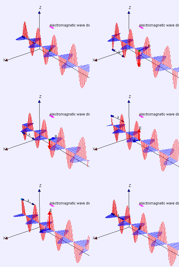
Light is actually a wave (more specifically, an electromagnetic (EM) wave). A wave (such as those on the ocean) is a clever way to transfer energy from one place to another without transferring matter. We will explore waves in another chapter. For now, you can think of light as Nature’s elegant solution for sending energy across the emptiness of space.
2 Colours, Wavelengths And Wavenumbers
2.1 Colour And Wavelength

Let’s move on to another question: How many colours are there? For example, in the figure alongside, how many colours can you count in the rainbow? While we often say the rainbow has seven colours, in reality there are infinitely many shades. To describe colours more precisely (and scientifically), we use something called a wavelength (\(\lambda\)), usually measured in micrometres (\(\mu\text{m}\)) or nanometres (nm). In this system, a typical red might have a wavelength of about 665 nm, and a typical green about 550 nm. The term ‘wavelength’ comes from the wave nature of light we touched on earlier.
You will also encounter another way to specify colour: the wavenumber (\(\nu\), measured in cm\(^{-1}\)). Wavenumbers are widely used in spectroscopy. It is worth becoming comfortable with switching between wavelengths and wavenumbers.
Finally, frequency, measured in Hertz (Hz), is yet another way to “label” colours. However, wavelength (or wavenumber) is more commonly used, possibly because it is easier for most of us to relate to lengths than to rates of oscillation.
2.2 Wavenumber
The wavelength refers to a length (dah) and is measured in a unit of length (usually \(\mu\text{m}\) or nm). The wavenumber expresses the same information by giving the number of wavelengths that will fit into 1 cm.
Let’s take an example:
Example 1 (Wavelength To Wavenumber) How many wavenumbers is a wavelength of 500 nm?
Solution:
\(\lambda = 500\) nm means that a wavelength occupies a length of 500 nm. So the number of wavelengths in 1 metre is given by:
\[ \text{Number of wavelengths in 1 m} = \dfrac{1}{500}\dfrac{1}{\text{nm}} =\dfrac{10^{9}}{500} \dfrac{1}{\text{m}} \]
Let’s convert this to the number of wavelengths in 1 cm:
\[ \text{Number of wavelength in 1 cm} = \dfrac{10^{9}}{500} \dfrac{1}{\text{m}} = \dfrac{10^{9}}{500}\dfrac{10^{-2}}{\text{cm}} = 20,000 \text{ cm$^{-1}$} \]
Exercise 1 (Convert To Wavenumber)
What is the wavelength of an electromagnetic wave whose wavenumber is \(10,000\) cm-1?
3 The Electromagnetic Spectrum
3.1 What Is The EM Spectrum?

Note the top portion that indicates how the various wavelengths interact with our atmosphere.
Note also the bottom portion that shows the relationship to a blackbody.
It turns out that there are far more colours/wavelengths than our eyes can detect. The part we can see (called the visible range) is only a small portion of all possible electromagnetic (EM) waves. All of the other EM waves together form what we call the electromagnetic spectrum.
The different wavelengths and regions of the EM spectrum are shown in the figure above. You are probably already familiar with many parts of it from everyday life, for example, microwaves for cooking or X‑rays for medical imaging.
All the colours/wavelengths of the EM spectrum travel through empty space at the same speed (\(c\)). However, they have different characteristics. For example, as you will see later, different wavelengths carry different amounts of energy, with energy decreasing as wavelength increases.
The differences become even more obvious when EM waves interact with materials (such as glass or water). Different wavelengths travel at different speeds in a material and may be absorbed or transmitted to varying degrees. These differences have a huge impact on how we use and interact with light.
3.2 Typical Values
It is useful to remember a typical value of a wavelength that represent the various bands. I have shown this in the table below:
| Region of EM Spectrum | Wavelength Range | Typical Wavelength |
|---|---|---|
| Radio waves | > 10 cm | 1 m |
| Microwaves | 1 mm – 10 cm | 5 cm |
| Infrared (IR) | 700 nm – 1 mm | 10 μm |
| Visible light | 400 – 700 nm | 550 nm |
| Ultraviolet (UV) | 10 – 400 nm | 100 nm |
| X-rays | 0.01 – 10 nm | 1 nm |
| Gamma rays | < 0.01 nm | 0.001 nm |
It is also useful to remember some typical wavelengths within the visible range:
| Colour | Approximate Wavelength |
|---|---|
| Red | 650 nm |
| Green | 550 nm |
| Blue | 450 nm |
| Violet | 400 nm |
4 Light & Matter
4.1 Wavelength dependant transmission
To highlight how differently various colours and wavelengths interact with matter, let’s take the example of light in water.
The reason the ocean appears blue is because water is quite picky about colour. In fact, the reason microwaves work for cooking is also related to water molecules absorbing microwaves very effectively (try putting a dry, empty glass into a microwave and you will notice it does not heat up).
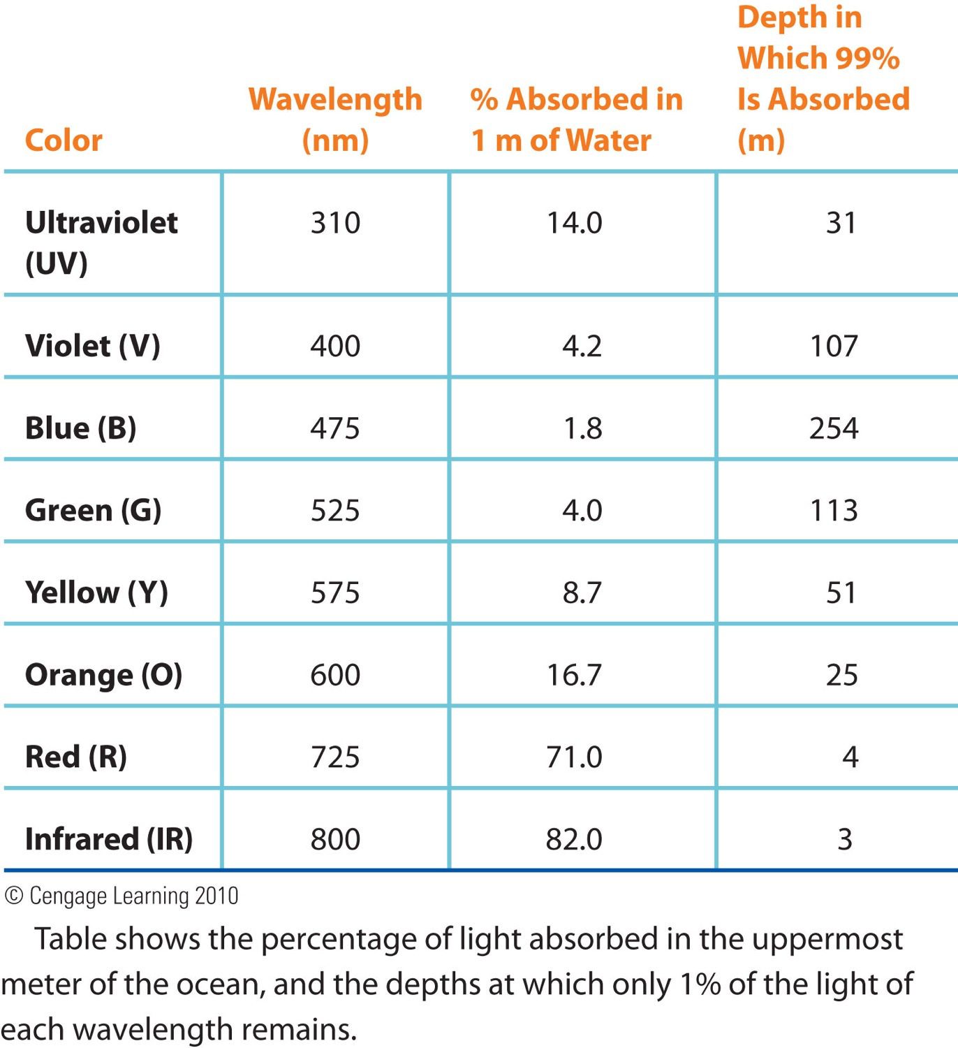
When I say picky, I mean that water is selective about how it absorbs different wavelengths. As shown in Table 3, red light is absorbed much more strongly than blue light. This means red penetrates the least, and blue penetrates the most. As a result, only blue light reaches the bottom and reflects back upwards.
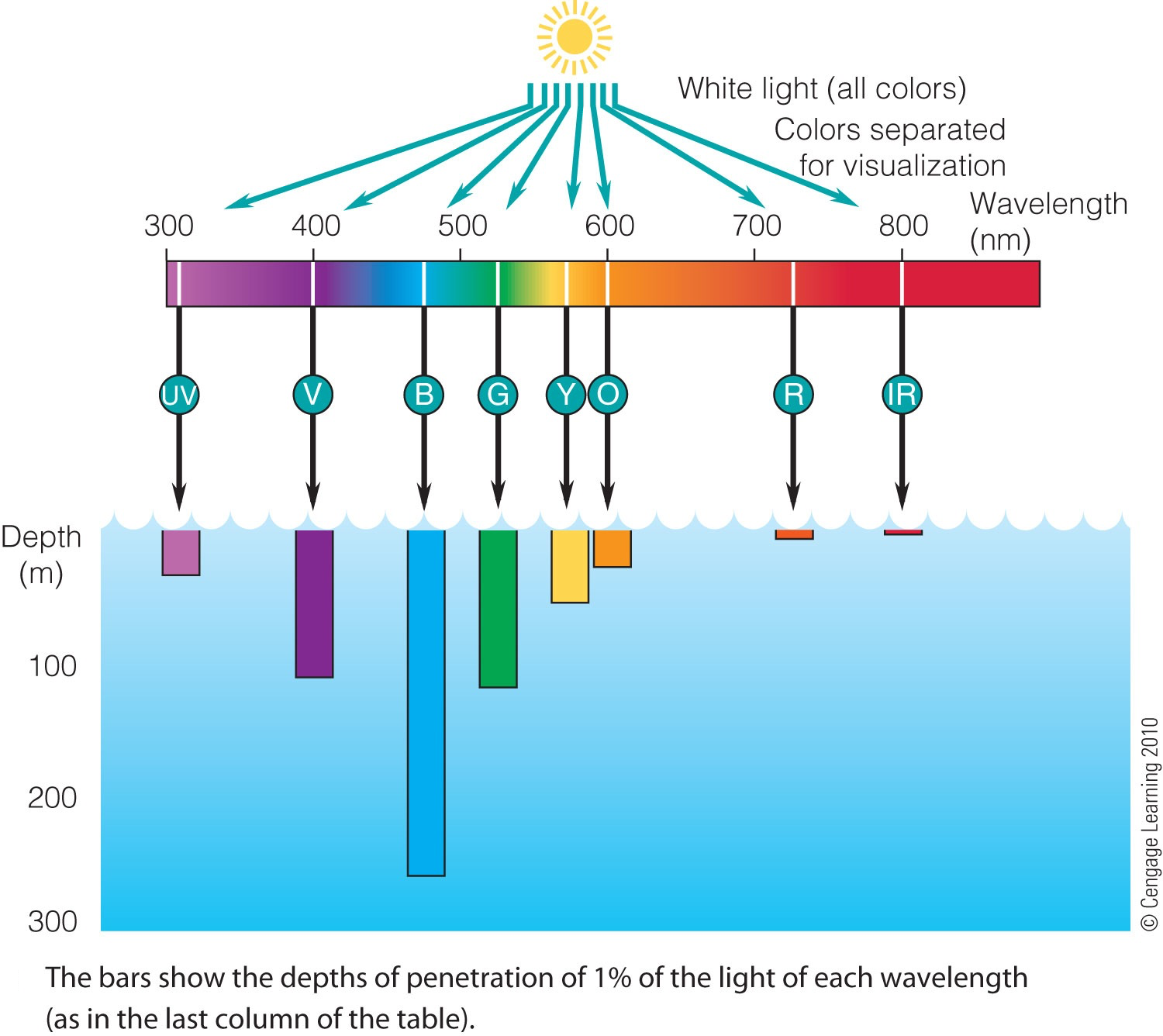
We will talk more about this in a later chapter, but it is worth noting that no wavelength is ever completely absorbed. In fact, absorption typically follows an exponential decay as dictated by the Beer-Lambert Law.
4.2 The Speed of Light
Light is one of the most remarkable and unique phenomena in nature. It is at the heart of foundational theories like quantum mechanics and special relativity.
The speed of light in vacuum is: \[ c = 2.998 \times 10^8 \text{m s}^{-1} \tag{1}\]
This speed is the absolute upper limit to how fast any signal, particle, or information can travel in our universe.
The speed of light in matter, however, can be different depending on the material.
4.3 Refractive Index
The speed of light in a material is always less than in vacuum. How much it slows is so important that materials are characterised by an optical refractive index defined by
where \(c\) is the speed of light in vacuum and \(v\) is the speed of light in the material.
The refractive index is wavelength-dependent, so most materials are dispersive for light.
| Material | Refractive Index \(n\) |
|---|---|
| Air | 1.0003 |
| Water | 1.33 |
| Glass | 1.5. |
| Diamond | 2.42 |
Dispersion
The speed of light in a material depends on its wavelength. Therefore, different colours of light travel through the material at different speeds and experience different refractive indices. This phenomenon is called dispersion.
5 Optical path length and phase
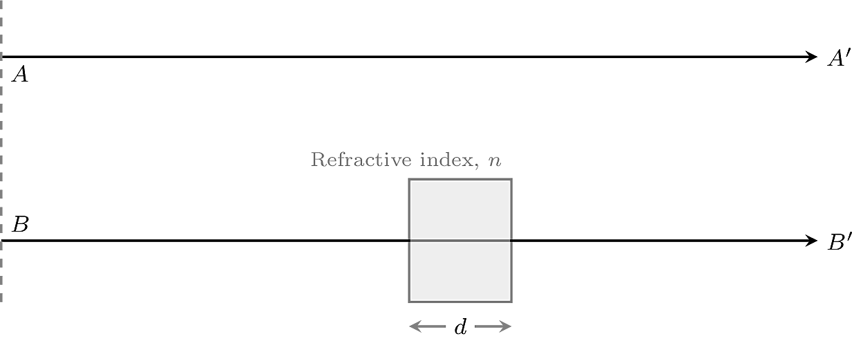
Consider two light beams, \(A\) and \(B\), of the same colour and vacuum wavelength \(\lambda_0\). The beams begin in phase and travel the same geometrical distance, as shown in Figure 5.
- Beam \(A\) travels entirely through air, which we approximate as having a refractive index of \(1\).
- Beam \(B\) passes through a slab of thickness \(d\) and refractive index \(n\).
The frequency of light does not change when the light enters the slab. Its speed and wavelength, however, decreases. To see this note that:
\[ v_{\text{medium}} =f\lambda_{\text{medium}} =\frac{c}{n}. \tag{3}\]
In air,
\[ c=f\lambda_0\Rightarrow f=\frac{c}{\lambda_0}. \]
Substituting this expression for \(f\) into Equation 3 gives
\[ \frac{c}{n} =\frac{c}{\lambda_0}\lambda_{\text{medium}}. \]
Hence,
\[ \lambda_{\text{medium}}=\frac{\lambda_0}{n}. \tag{4}\]
The wavelength in the material is therefore smaller than the wavelength in air.
As a consequence, more wave cycles of \(\lambda_{\text{medium}}\) fit into a distance \(d\) inside the material than into the same distance in air.
Each time a wave travels one wavelength, its phase advances by \(2\pi\). Over the distance \(d\), beam \(A\) accumulates the phase
\[ \phi_A=2\pi\frac{d}{\lambda_0}. \tag{5}\]
Over the same distance, beam \(B\) accumulates the phase
\[ \begin{aligned} \phi_B &=2\pi\frac{d}{\lambda_{\text{medium}}} \\ &=2\pi\frac{nd}{\lambda_0}. \end{aligned} \tag{6}\]
The phase accumulated by beam \(B\) while travelling a geometrical distance \(d\) through the material is therefore the same as the phase it would accumulate while travelling a distance \(nd\) in air. This equivalent distance is called the optical path length:
What is the phase difference between \(A\) and \(B\)?
It is useful to calculate the phase difference between beams \(A\) and \(B\). Once we know this difference, we can determine how to bring the beams back into phase.
Beam \(B\) passes through a distance \(d\) in a material of refractive index \(n\), giving it an optical path length of \(nd\). Beam \(A\) travels the corresponding distance \(d\) through air. Therefore, the optical path difference between the beams is
\[ \mathrm{OPD}=nd-d=(n-1)d. \tag{8}\]
A path difference of one wavelength corresponds to a phase difference of \(2\pi\). Therefore, the phase difference between the beams is
\[ \begin{aligned} \Delta\phi &=\phi_B-\phi_A \\ &=\frac{2\pi}{\lambda_0}\,\mathrm{OPD} \\ &=\frac{2\pi}{\lambda_0}(n-1)d. \end{aligned} \tag{9}\]
If we want beams \(A\) and \(B\) to have the same phase, their phase difference must be an integer multiple of \(2\pi\):
\[ \Delta\phi=2\pi m, \qquad m=0,\pm1,\pm2,\ldots \]
Equivalently, their optical path difference must be an integer multiple of the vacuum wavelength:
\[ (n-1)d=m\lambda_0. \tag{10}\]
6 Instruments
6.1 Diffraction Grating
As we have discussed before, the various wavelengths contained in a signal can carry important information. A diffraction grating is a simple yet powerful instrument that allows us to separate light into its component wavelengths.
A diffraction grating is a piece of transparent material on which a large number of equally spaced, parallel lines have been ruled. The distance between these lines is called the grating line spacing, \(d\).
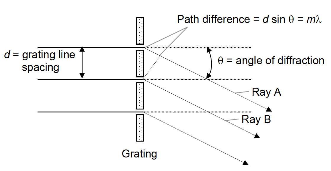
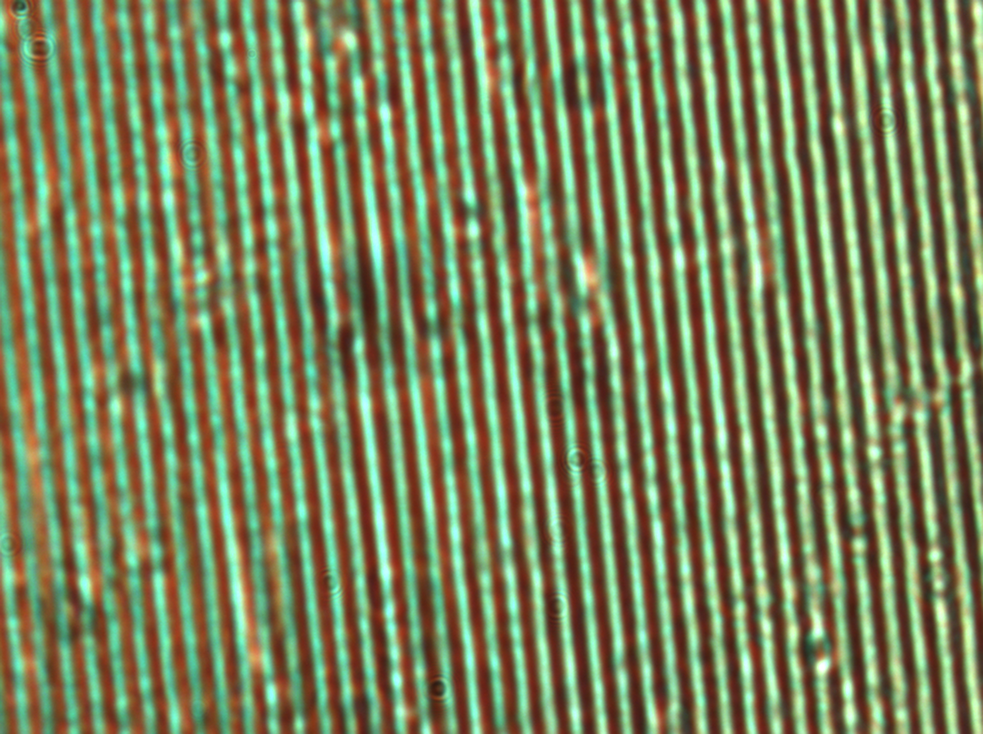
(Right) A diffraction grating at 100× magnification. The width of the transparent portion is 785 nm, with a total period of 1666 nm.
When light strikes the grating, it is diffracted by the parallel lines, producing beams that emerge at various angles relative to the incident beam. If the diffracted rays from adjacent lines interfere constructively (that is, they are in phase), a bright image of the source is formed.
The working of a diffraction grating is described by the following grating equation:
| \(m\) | Diffraction order (\(0, 1, 2, \ldots\)) | |
| \(\lambda\) | Wavelength of light | m |
| \(d\) | Grating line spacing | m |
| \(\theta\) | Diffraction angle | rad |
Derivation of the Grating Equation
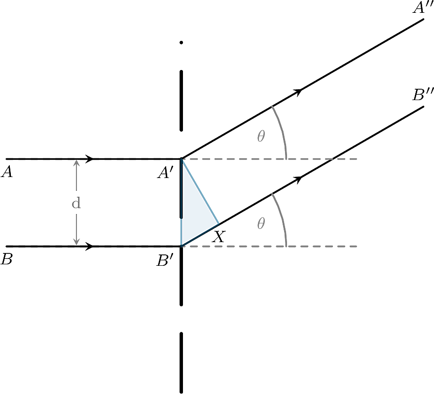
Let me take you through the derivation of the grating equation, because it is a nice example of the importance of path differences.
If you look at Figure 7, you will see that if rays \(A\) and \(B\) are to produce a bright spot, the path difference between them must be a multiple of the wavelength \(\lambda\).
Notice that the only difference in path occurs between \(B'\) and \(X\). So, the condition for a bright spot at angle \(\theta\) is that
\[ B'X = m \lambda, \]
which gives
\[ d \sin \theta_m = m \lambda. \tag{12}\]
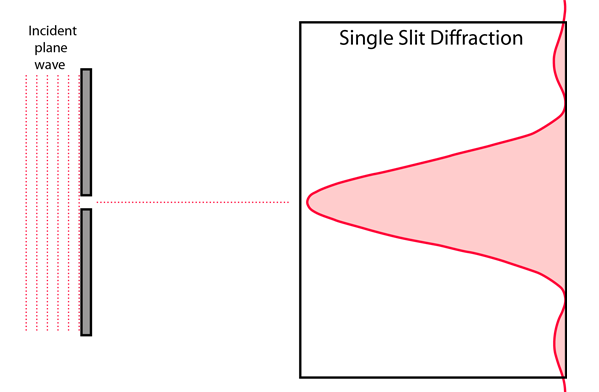
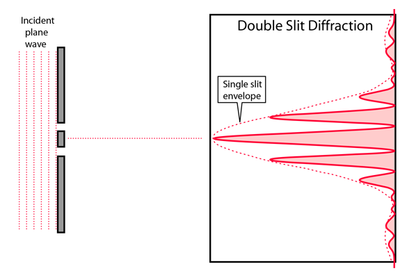
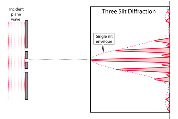
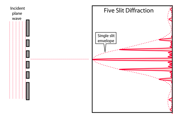
Why do we need so many slits?
Figure Figure 8 shows the intensity (i.e. brightness) pattern you expect when you send light through one slit and through multiple slits.
If you increase the number of slits to thousands, you end up with a sharp set of bright points (called orders). The zeroth-order is the brightest and indicates the direction the light would have gone if it had not been diffracted. The angles to the higher orders are given by the grating equation:
Diffraction grating at non-normal incidence
When light is incident on a diffraction grating at an angle, rather than perpendicular to its surface, Equation 11 must be modified slightly.
Suppose the incident light makes an angle \(\alpha\) with the grating normal.then the grating equation becomes
\[ d\left(\sin\theta_m-\sin\alpha\right)=m\lambda, \qquad m=0,\pm1,\pm2,\ldots \tag{13}\]
Therefore,
\[ \sin\theta_m=\sin\alpha+\frac{m\lambda}{d}. \]
So, at non-normal incidence, the diffraction orders do not appear symmetrically on either side of the grating normal. For instance, the zeroth-order beam (with \(m=0\)) appears at \(\theta_0=\alpha\).
6.2 Interferometry
Interferometry is a powerful technique for making precise measurements. I know of at least two Nobel Prizes have been awarded for advances in interferometry, one for the Michelson interferometer in 1907 and more recently for the groundbreaking discoveries of LIGO in 2017. You may not realise it, but every time you use an FTIR spectrometer, you are making use of an interferometer.
At its heart an interfermeter is simply a device that keeps track of path and phase differences between waves that travel along different routes. In this section, I will introduce you to one of the most basic interferometers: the Michelson Interferometer. By understanding this simple case, you will be able to appreciate how interferometry works in general.

The Michelson interferometer has two mirrors, one of which can be moved. When set up, the signal at the detector looks like in Figure 9. It can easily be shown that the signal at the detector depends on the path difference between the two arms of the interferometer, i.e. \(d_1 - d_2\), where \(d_1\) and \(d_2\) are the distances to the mirrors. More specifically, when \(d_1 - d_2\) changes by \(\f{\lambda}{4}\), the total path difference changes by \(\f{\lambda}{2}\). By adjusting the length of the movable mirror arm, we can cycle through conditions of constructive and destructive interference.
A typical experiment involves moving the mirror slowly, passing through several cycles of constructive and destructive interference, and counting the number of fringes (bright-to-dark transitions). From this count, the distance moved by the mirror can be determined with extremely high precision.
Footnotes
The term radiation refers to anything that carries energy away from its source. It is used for light, but also for nuclear processes, because both involve energy being carried away.↩︎